| Items |

K6500x12
Ready K 6500, 152 Millimeter (mm) Fully Opened Length (La) Working Cylinder with Pressure Accumulators
List Price Quote
|

K6500x25
Ready K 6500, 178 Millimeter (mm) Fully Opened Length (La) Working Cylinder with Pressure Accumulators
List Price Quote
|

K6500x38
Ready K 6500, 204 Millimeter (mm) Fully Opened Length (La) Working Cylinder with Pressure Accumulators
List Price Quote
|

K6500x50
Ready K 6500, 228 Millimeter (mm) Fully Opened Length (La) Working Cylinder with Pressure Accumulators
List Price Quote
|

K6500x63
Ready K 6500, 254 Millimeter (mm) Fully Opened Length (La) Working Cylinder with Pressure Accumulators
List Price Quote
|
|
Description
|
N/A
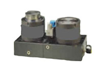
Cylinders with stem controlled movement can stop at the desired working position, with the possibility of deciding when stem withdrawal is to take place by means of an electric signal, in accordance with the application that is being executed.
Each unit has the following elements:- Working Cylinder
- Pressure Accumulator
- Adaptor Plate
- Hydraulic Valve
|
|
Brands
|
N/A
Ready
|
|
Additional Information
|
N/A
The adapter plate locates each unit and links it to the other units in the system. The working cylinder, which is full of oil, is connected through the adapter plate to the pressure accumulator. This is subjected in one of its parts to nitrogen gas pressure, thus providing pressure for the whole system. The accumulator has the capacity to absorb the whole of the volume of oil displaced by the working cylinder.
The working cylinder is activated by the movement of the press, displacing the hydraulic volume freely through the adapter plate up to the pressure accumulator. Once the working stroke has been attained, the hydraulic valve, which is controlled by means of an electric signal, stops the return of hydraulic fluid from the accumulator to the working cylinder, at which point the piston movement stops. When the hydraulic valve opens once again, the hydraulic volume returns to the working cylinder, thus bringing about the return of the stem to its stand-by position.
The pressure accumulator is regulated in accordance to pressure device norms, as it is charged with nitrogen gas at a pressure of 150 Bar.
|
|
Application
|
N/A
Work Holding
|
|
Force Increase by Temperature
|
N/A
0.33 %/°C
|
|
Maximum Stem Speed
|
N/A
10 m/min
|
|
Maximum Charging Pressure
|
N/A
150 bar
|
|
Minimum Charging Pressure
|
N/A
50 bar
|
|
Fully Closed Force (Fc)
|
N/A
7280 daN
|
N/A
7885 daN
|
N/A
8405 daN
|
N/A
8825 daN
|
N/A
9220 daN
|
|
Maximum Stroke Length
|
N/A
12 mm
|
N/A
25 mm
|
N/A
38 mm
|
N/A
50 mm
|
N/A
63 mm
|
|
Fully Opened Length (La)
|
N/A
152 mm
|
N/A
178 mm
|
N/A
204 mm
|
N/A
228 mm
|
N/A
254 mm
|
|
Fully Closed Length (Lc)
|
N/A
140 mm
|
N/A
153 mm
|
N/A
166 mm
|
N/A
178 mm
|
N/A
191 mm
|
|
Fully Opened Force (Fa)
|
N/A
6500 daN
|
|
Fully Opened Force (Fa) Tolerance (±)
|
N/A
5 %
|
|
Medium Pressure
|
N/A
Nitrogen Gas (N2) Oil
|
|
Nitrogen Gas (N2) Nominal Pressure
|
N/A
150 bar
|
|
Rod Seal Area
|
N/A
44.18 cm²
|
|
Maximum Working Temperature
|
N/A
60 ºC
|
|
Product Code
|
N/A
|


