| Items |

REC 62-AA
READY HiPro REC62 CB1 1.125" Long Standard Bender
List Price $490.00
|

REC 62-CC
READY HiPro REC62 CB1 3.500" Long Standard Bender
List Price $1,055.00
|

REC 62-DD
READY HiPro REC62 CB1 6.000" Long Standard Bender
List Price $1,330.00
|

REC 100-AA
READY HiPro REC100 CB1 1.500" Long Standard Bender
List Price $585.00
|

REC 100-BB
READY HiPro REC100 CB1 4.000" Long Standard Bender
List Price $1,265.00
|
|
Description
|
N/A
- Designed to produce over 500,000 parts per year
- Standard CB1 87° Rocker angle produces consistent 90° bends in mild steel
- Many Standard lengths and Rocker diameters available
- Hardened (Rc 48-52) A2 Tool Steel Saddle with counter-bored mounting holes installed
- S7 Tool Steel Full Hardened (Rc 56 to 62) Rocker for long life
- Standard models are stocked for fast delivery
- 3D CAD models available
|
|
Features
|
N/A
- Rockers: fully hardened (Rc 56 to 62), S-7 tool steel.
- Saddles: fully hardened,(Rc 48 to 52) A-2 tool steel. Counterbored mounting holes per patterns. Flush mount lube fittings.
- Rockers and saddles are CNC ground for precision and interchangeability.
- Rocker angle is 87º on all standard benders. This allows for 3º of overbend to produce consistent 90º forms in mild steel. Harder steel or larger part radii may require more overbend. Rocker angles can be specified at time of order or altered by the diemaker.
|
|
Rocker Diameter
|
N/A
0.625 in
|
N/A
0.625 in
|
N/A
0.625 in
|
N/A
1.000 in
|
N/A
1.000 in
|
|
Part Thickness (PT)
|
N/A
0.010 to 0.042 in
|
N/A
0.010 to 0.042 in
|
N/A
0.010 to 0.042 in
|
N/A
0.043 to 0.075 in
|
N/A
0.043 to 0.075 in
|
|
Part Height Check (PH)1
|
N/A
0.250 in
|
N/A
0.250 in
|
N/A
0.250 in
|
N/A
0.390 in
|
N/A
0.390 in
|
|
In Stock Length (X)
|
N/A
1.125 in
|
N/A
3.500 in
|
N/A
6.000 in
|
N/A
1.500 in
|
N/A
4.000 in
|
|
Minimum Length
|
N/A
1.125 in
|
N/A
1.125 in
|
N/A
1.125 in
|
N/A
1.500 in
|
N/A
1.500 in
|
|
Maximum Length (X)
|
N/A
24 in
|
|
Saddle Width (SW)
|
N/A
2.125 in

|
N/A
2.125 in

|
N/A
2.125 in

|
N/A
2.875 in

|
N/A
2.875 in

|
|
Saddle to Front (SF) Width
|
N/A
0.750 in

|
N/A
0.750 in

|
N/A
0.750 in

|
N/A
1.125 in

|
N/A
1.125 in

|
|
Saddle to Key (SK) Width
|
N/A
1.375 in

|
N/A
1.375 in

|
N/A
1.375 in

|
N/A
1.750 in

|
N/A
1.750 in

|
|
Saddle Height (SH)
|
N/A
0.875 in

|
N/A
0.875 in

|
N/A
0.875 in

|
N/A
1.375 in

|
N/A
1.375 in

|
|
Gib Length (GL)
|
N/A
1.125 in

|
N/A
1.125 in

|
N/A
1.125 in

|
N/A
1.500 in

|
N/A
1.500 in

|
|
Rocker Angle
|
N/A
87 º
|
|
Rocker Dimension (B)
|
N/A
0.212 in

|
N/A
0.212 in

|
N/A
0.212 in

|
N/A
0.339 in

|
N/A
0.339 in

|
|
Rocker Dimension (C)
|
N/A
0.195 in
|
N/A
0.195 in
|
N/A
0.195 in
|
N/A
0.312 in
|
N/A
0.312 in
|
|
Rocker Dimension (J)
|
N/A
0.246 in
|
N/A
0.246 in
|
N/A
0.246 in
|
N/A
0.393 in
|
N/A
0.393 in
|
|
Note
|
N/A
Tapped mounting holes available as specials.
For metric mounting holes, ready high production benders
|
|
Length Style
|
N/A
AA
|
N/A
CC
|
N/A
DD
|
N/A
AA
|
N/A
BB
|
|
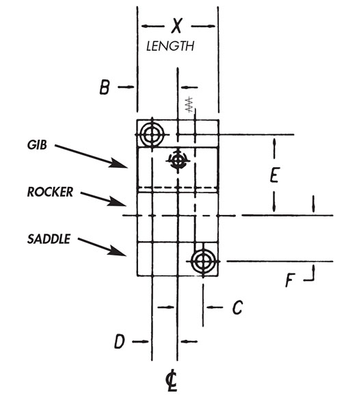
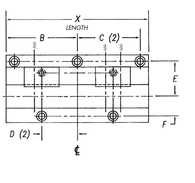
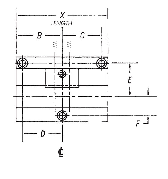
Dimension (B)
|
N/A
0.562 in
|
N/A
1.750 in
|
N/A
3.000 in
|
N/A
0.750 in
|
N/A
2.000 in
|
|
Dimension (C)
|
N/A
0.354 in
|
N/A
1.514 in
|
N/A
2.764 in
|
N/A
0.472 in
|
N/A
1.724 in
|
|
Dimension (D)
|
N/A
0.354 in
|
N/A
0.875 in
|
N/A
1.500 in
|
N/A
0.472 in
|
N/A
1.724 in
|
|
Dimension (E)
|
N/A
1.181 in
|
N/A
1.181 in
|
N/A
1.181 in
|
N/A
1.476 in
|
N/A
1.476 in
|
|
Dimension (F)
|
N/A
0.551 in
|
N/A
0.551 in
|
N/A
0.551 in
|
N/A
0.846 in
|
N/A
0.846 in
|
|
Socket Head Cap Screw Dimensions
|
N/A
#10
|
N/A
#10
|
N/A
#10
|
N/A
1/4 in
|
N/A
1/4 in
|
|
Thickness
|
N/A
25 to 19 gauge
|
N/A
25 to 19 gauge
|
N/A
25 to 19 gauge
|
N/A
19 to 14 gauge
|
N/A
19 to 14 gauge
|
|
Mounting Diagram
|
N/A

Ready AA Length Style High Production Standard Lenght Bender
|
N/A

Ready CC and DD Length Style High Production Standard Lenght Bender
|
N/A

Ready CC and DD Length Style High Production Standard Lenght Bender
|
N/A

Ready AA Length Style High Production Standard Lenght Bender
|
N/A

Ready BB Length Style High Production Standard Lenght Bender
|
|
Product Code
|
N/A
RB
|


