Manufacturer Part# / Cross Reference Search

Please use this search function to find READY die set components that are equivalent to commonly used pins, bushing, ISO Springs, and Gas Springs from other manufacturers.

Please Note: We believe this cross reference to be accurate. Please review the specifications to ensure the item will work in your application. Gas Spring equivalents were based on body dimensions, on contact force and stroke length.
  • Designed to produce up to one million parts, ideal for most stamping dies.
  • In stock lengths: 12", 24" and up to 36" long.
  • Segment stock lengths to reduce your tooling budget; quick delivery.
  • Benders are now less expensive than wipe tooling.
Unit of Measure

Features

Features

N/A
  1. Rockers: fully hardened (Rc 56 to 62), S-7 tool steel.
  2. Saddles: machinable thru hardened steel; mounting holes left for diemaker to locate where needed. Contact Ready Engineering for suggestions.
  3. Saddle socket is coated for lubrication and long life. Saddle has flush mount lube fittings.
  4. Rockers and saddles are CNC ground for precision and interchangeability.
  5. Rocker angle is 87º on all standard benders. This allows for 3º of overbend to produce consistent 90° forms in mild steel. Harder steel or larger part radii may require more overbend. Rocker angles can be specified at time of order or altered by the diemaker.

Specifications

Rocker Diameter

N/A 3.000 in

Part Thickness (PT)

N/A 0.210 to 0.250 in
Part Height Check (PH)1 N/A 1.160 in

In Stock Length (X)

N/A 12 in24 in36 in

Minimum Length

N/A 3.500 in

Maximum Length (X)

N/A 36 in

Saddle Width (SW)

N/A 6.875 in Saddle-Width.jpg

Saddle to Front (SF) Width

N/A 2.750 in Saddle-to-Front.jpg

Saddle to Key (SK) Width

N/A 4.125 in Saddle-to-Key.jpg

Saddle Height (SH)

N/A 3.375 in Saddle-Height.jpg

Gib Length (GL)

N/A 3.500 in Gib-Length.jpg

Rocker Angle

N/A 87 º

Rocker Dimension (B)

N/A 1.017 in a1490.jpg

Rocker Dimension (C)

N/A 0.936 in

Rocker Dimension (J)

N/A 1.179 in

Note

N/A 12, 24" & 36" lengths in stock, 2", 2 1/2" and 3" Diameter Rockers

Additional Information

N/A
  • Designed so you can segment to shorter custom lengths.
  • Minimum segment size is the Gib Length (GL).
  • Custom lengths available, specify.

Product Code

N/A RB

Dart Stiffeners

Dart Stiffener Overview

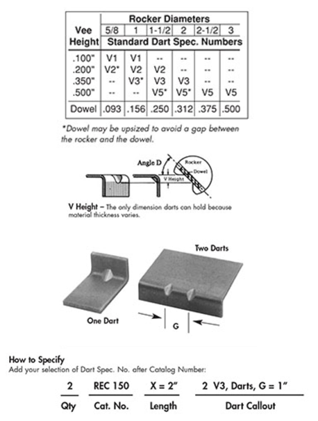
N/A Standard darts are shown in the table below or you can specify your own angle and dowel size

Darts are rolled into the part during bending, reducing springback and stiffening the part. Darts are produced using dowels through the rocker and require relief grooves in the anvil. The side angles of the darts are a function of the angle and size of the dowel.

Darts are available as spcifiable extras on all READY Benders®. Darts are central on a 45° angle unless detailed.

Eliminate:
  • Galling and Maintenance
  • Unattractive Parts
  • Secondary Operations
Table of specification info relating to Dart Stiffeners, an option for all READY Benders

Tooth Benders

Tooth Bender Overview

N/A Tooth benders use special rockers to eliminate die/part interferences. Often the saddle needs to be made special without gibs in one peice. Send prints for a quotation.
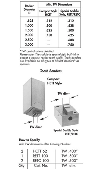

Specification info for Tooth Benders, an option for all READY Benders

Over Square Bends

Over Square Bend Overview

N/A The READY Bender's ® ability to bend 45° beyond ninety (135° PA) is one of its greatest features. Customers buy standard benders and do this simple alteration themselves, adding a degree or two of overbend to the rocker. This easy alteration is done by grinding the bending jaw of the rocker, while not distrubing the working radius of the bending lobe (grind past centerline).

For assistance, call READY Technology and we will give you the necessary dimensions to make this alteration

Information relating to the specification of over square bends for READY Benders

Pad Benders

Pad Benders Overview

N/A Pads can help in many bender applications. By activating the bender on top of a pad, you isolate the rocker from the part on the critical holddown surface.
NO CONTACT = NO MARK

Important Pad Functions
  1. Pads can be design to match a part's "irregular" shape on one side yet be flat and parallel on the surface that the bender contacts.
  2. Eliminates rocker contact and impact on part holddown surface
  3. To protect a part cutout or hole from distortion do to its proximity to the bend line.
  4. To eliminate humping of the material when the application distates upsizing the rocker diameter. The pad provides holddown pressure close to the bend radius
  5. To match a standard rocker diameter ti the Zee bend or offset vertical height. Allows the use of standard rockers versus making specials.

When Using Pads, READY Technology Reommends:
  1. Locate the pad and its shoulder screws/spools as close as possible to the tangency point of the radius. This location and bushings or guides will prevent the pad from slipping
  2. Springs to lift the pad should work separately from the spring return of the bender.
  3. Additional part holddown may be required in some special applications (pilots, die springs or nitrogen cylinder).
Diagram of pad benders, an option on READY Benders
  • 1 To use standard benders, PH should exceed these dimensions. Fax prints for specials.